

Structured cabling is a standardised, hierarchical approach to building a telecommunications infrastructure that supports voice, data and fibre connectivity across a site. Unlike point-to-point wiring, it organises all cabling through defined subsystems — entrance facilities, distribution rooms, backbone and horizontal runs — so that any outlet can be traced, tested and changed without disrupting the rest of the network.
Unmanaged, ad-hoc cabling is one of the most common sources of unplanned downtime in business environments. When a technician cannot identify which patch cord connects which device, a simple move becomes a risk event. Structured cabling solves this by imposing order from the outset: every link is documented, labelled and installed to a recognised standard such as ANSI/TIA-568 or ISO/IEC 11801, which means performance is predictable and changes are controlled. The result is a physical network layer that supports your IT operations today and scales with your business tomorrow without requiring a full rewire.
What Structured Cabling Is (and why it's different)
Point-to-point wiring connects each device directly to its destination with a dedicated cable run. It works at small scale but degrades rapidly as a site grows: cables multiply, labelling lapses, and the infrastructure becomes a tangle that no single person fully understands. Structured cabling replaces that model with a planned hierarchy in which all cabling flows through defined distribution points — telecommunications rooms, cross-connects and patch panels — before reaching the end device. Every run has a known origin, a known destination and a documented path.
The practical difference is most visible during moves, adds and changes (MACs). In a point-to-point environment, relocating a workstation may require running a new cable across the ceiling. In a structured environment, it means patching a different port in the telecommunications room — a task measured in minutes rather than hours.
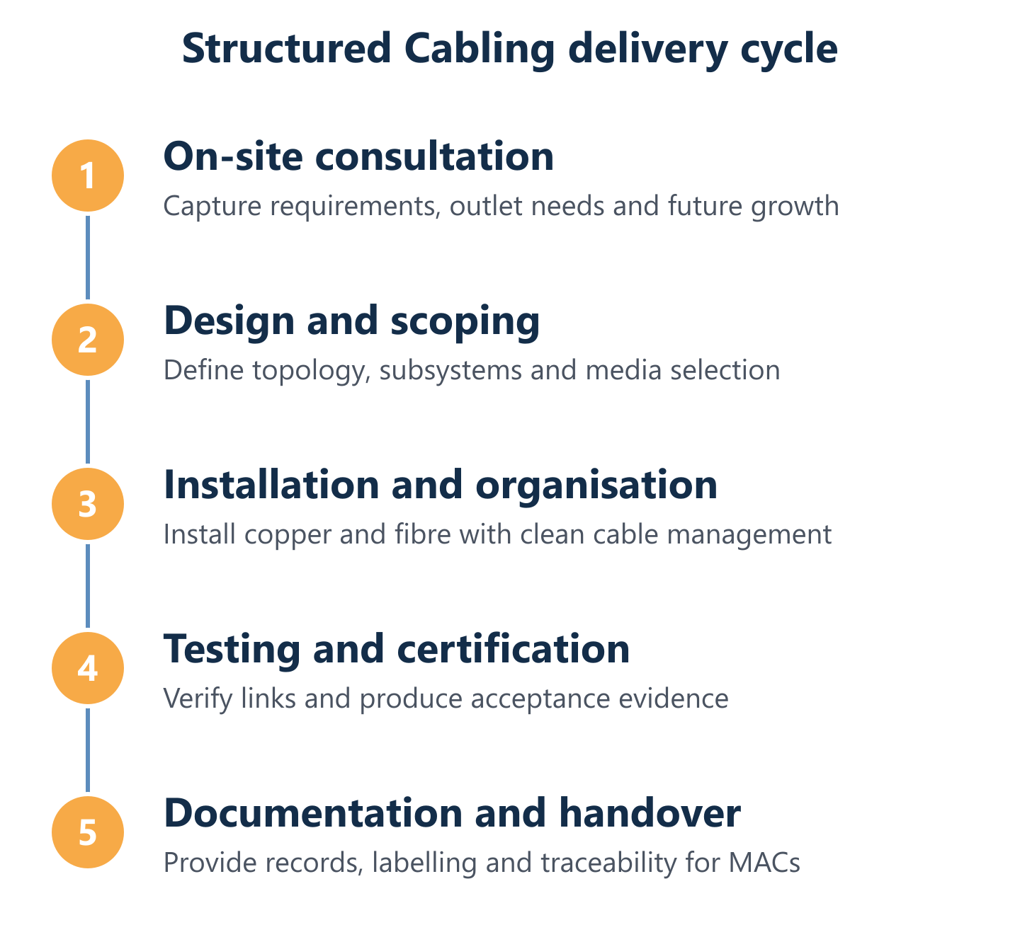
At Impulso Tecnológico, every structured cabling engagement begins with a free on-site consultation to map current connectivity, identify growth requirements and design a layout that supports efficient MACs for voice, data and fibre from day one.
| Criterion | Point-to-Point Wiring | Structured Cabling |
|---|---|---|
| Traceability | Low — cables rarely labelled end-to-end | High — every run documented and labelled to standard |
| MAC speed | Slow — often requires new cable runs | Fast — patch panel reconfiguration in minutes |
| Downtime risk | High — wrong cable pulled affects live services | Low — changes isolated at distribution point |
| Scalability | Poor — complexity grows with each addition | Good — subsystems absorb growth without rewiring |
| Standards compliance | None — ad hoc by nature | ANSI/TIA-568, ISO/IEC 11801 or EN 50173 |
| Airflow and rack hygiene | Often compromised by cable clutter | Maintained through managed cable trays and panels |
Structured Cabling definition and core purpose
Structured cabling is a complete, standards-governed telecommunications cabling system designed to serve multiple hardware uses simultaneously — voice, data, video and building management — through a single, unified infrastructure. Its defining characteristic is hierarchy: rather than connecting devices directly to one another, all cabling terminates at defined distribution points that create a logical, manageable topology.
The core purpose is predictability. When cabling is installed to a recognised standard, every link performs within known parameters regardless of which vendor's equipment is connected. This vendor-neutral design is what allows structured cabling to outlast multiple generations of active hardware. A well-installed Category 6A copper run certified to ANSI/TIA-568 standards will support 10 Gigabit Ethernet today and remain valid infrastructure for the next fifteen to twenty years of technology refresh cycles.
Hierarchy and architecture: backbone, rooms and work areas
The architecture of a structured cabling system flows from the building entrance inward through a series of distribution levels. At the top sits the Main Distribution Area (MDA) or main cross-connect, which aggregates all backbone cabling. Intermediate Distribution Areas (IDAs) or intermediate cross-connects serve floors or zones, and Horizontal Distribution Areas (HDAs) connect to individual work area outlets via horizontal cabling runs.
In a single-floor office, the hierarchy may collapse to a single telecommunications room (TR) feeding all outlets directly. In a multi-floor or campus environment, separate Building Distributors (BDs) and Floor Distributors (FDs) maintain the hierarchy while keeping each segment within its permitted length limits. This layered design means a fault or change at one level does not cascade unpredictably through the rest of the system — a property that directly supports network stability and planned maintenance windows.
Point-to-point vs Structured Cabling: day-to-day impacts
The operational gap between point-to-point and structured cabling becomes most apparent when a business relocates a team, adds workstations or decommissions a department. In a point-to-point environment, each of these events typically requires a site visit, a new cable pull and an undocumented change that makes the next intervention harder. Over time, abandoned cables accumulate in cable trays, restricting airflow and increasing the risk that a live cable is accidentally disconnected.
Structured cabling centralises all change activity at the patch panel in the telecommunications room. A MAC is executed by moving a patch cord between labelled ports — the permanent horizontal run remains untouched. This approach reduces human error, shortens mean time to resolve connectivity faults, and keeps cable trays clear enough to maintain adequate airflow around network equipment. For businesses that run frequent organisational changes, the cumulative time saving across a year of MACs is substantial.

Standards, components and real deployment choices
Delivering a structured cabling system that will perform reliably over its intended lifespan requires aligning every design decision — media choice, subsystem layout, termination method and testing protocol — with the applicable standard. The two dominant international frameworks are ANSI/TIA-568 (North American origin, widely adopted globally) and ISO/IEC 11801 (international), with EN 50173 serving as the European harmonised equivalent. Each defines channel performance, component grades, maximum run lengths and test parameters that must be met before a system is accepted.
At Impulso Tecnológico, our structured network cabling installations in Spain cover Categories 5e, 6 and 7 copper as well as multimode and single-mode fibre optic cabling. We select media and topology based on your site layout, current bandwidth requirements and a realistic projection of future growth — not a generic bill of materials.
- Assess site requirements: floor plans, user density, distance between distribution rooms and work areas, and any existing infrastructure to be retained or removed.
- Select applicable standard: confirm whether ANSI/TIA-568, ISO/IEC 11801 or a project-specific specification governs the installation and testing criteria.
- Design subsystem layout: position entrance facilities, telecommunications rooms and distribution areas to keep horizontal runs within the 90-metre permanent link limit.
- Choose media grades: match copper category and fibre type to bandwidth targets, distance constraints and budget, with a margin for future upgrade.
- Install, terminate and test: every link certified against the chosen standard using calibrated test equipment, with results recorded for handover documentation.
- Document and label: produce as-built drawings, port schedules and test records that make future MACs traceable and auditable.
Standards that govern design and performance outcomes
ANSI/TIA-568 is the primary North American standard for commercial building telecommunications cabling. Its current revision (ANSI/TIA-568-C.0 for generic requirements, -C.1 for commercial buildings) defines subsystem boundaries, recognised cabling types, connector interfaces and channel performance parameters. ISO/IEC 11801 covers the same ground at international level and is the basis for EN 50173, the European harmonised series.
In practical terms, standards compliance means three things for a project: first, that the installed channel will interoperate with any standards-compliant active equipment; second, that performance targets (insertion loss, return loss, crosstalk margins) are verified by test, not assumed; and third, that the documentation produced at handover is structured enough to support warranty claims and future audits. A system installed and certified to ANSI/TIA-568 or ISO/IEC 11801 is also a prerequisite for most manufacturer extended-warranty programmes, which can extend component guarantees to fifteen or twenty-five years.
Core subsystems: EF, TR/TE, backbone, horizontal and work area
ANSI/TIA-568 defines the structured cabling system through six subsystems, each with a specific scope and set of constraints:
- Entrance Facility (EF): the point where external service provider cabling enters the building and connects to the internal infrastructure. Houses demarcation equipment and protectors.
- Telecommunications Room (TR) / Telecommunications Enclosure (TE): the distribution point serving a floor or zone. Contains patch panels, cross-connects and active equipment. The TR is the hub for all horizontal cabling in its area.
- Backbone Cabling: connects TRs to the main cross-connect (MDA) and between buildings. Carries aggregated traffic and typically uses fibre for longer inter-floor or inter-building runs.
- Horizontal Cabling: runs from the TR/TE to the telecommunications outlet at the work area. Maximum permanent link length is 90 metres for balanced twisted-pair; total channel (including patch cords) must not exceed 100 metres.
- Work Area (WA): the space between the telecommunications outlet and the end device. Includes patch cords, adapters and equipment cords — components that are not permanently installed and are therefore excluded from the permanent link test.
Media and topology choices: copper categories and fibre types
Copper twisted-pair remains the dominant horizontal cabling medium for most business environments. Category 5e supports 1 Gigabit Ethernet to 100 metres and is adequate for low-density, low-bandwidth applications. Category 6 raises the ceiling to 10 Gigabit Ethernet at distances up to 55 metres in a fully populated environment. Category 6A extends 10GbE to the full 90-metre permanent link and is the current recommended baseline for new installations. Category 7 and 7A use shielded construction to support 40GbE and beyond, though connector compatibility requires careful specification.
For backbone runs and any horizontal segment exceeding copper distance limits, fibre is the correct choice. Multimode fibre (OM3 or OM4, 50/125 µm, optimised for 850 nm laser sources) covers inter-floor backbone distances up to several hundred metres at 10GbE or 40GbE. Single-mode fibre (OS2, 9/125 µm) is appropriate for campus or inter-building links where distances exceed multimode capability or where future 100GbE or beyond is anticipated. Impulso Tecnológico supplies and installs both copper and fibre cabling, selecting the appropriate grade based on your site topology and long-term maintainability goals.
Planning, documentation and operational benefits
A structured cabling project that is well scoped before installation begins will cost less to maintain over its lifetime than one that is designed on the fly. The planning phase determines outlet counts, room locations, cable routes, labelling conventions and testing acceptance criteria — decisions that, once the cables are in the ceiling, are expensive to revisit. Documentation produced at handover is not a formality; it is the operational asset that makes every future MAC faster and safer.
Impulso Tecnológico delivers certified network cabling practices across business environments in Spain, with more than fifteen years of structured cabling installations ranging from single-workplace deployments to infrastructure serving thousands of users. Our delivery model includes clean cable management, removal of abandoned cables, installation of cabling trays, and ongoing network maintenance — so the system remains reliable as your business changes.
- Start with a free on-site consultation to establish current state, user density, room layout and any legacy cabling to be retained or removed.
- Define outlet counts and locations based on current workstation positions and a realistic growth projection for the next three to five years.
- Confirm telecommunications room positions so that all horizontal runs stay within the 90-metre permanent link limit without requiring consolidation points that add complexity.
- Agree labelling conventions before installation begins — consistent port-to-outlet labelling is the single most important factor in MAC efficiency after handover.
- Specify test acceptance criteria aligned to the chosen standard (ANSI/TIA-568 or ISO/IEC 11801) so that certification records are unambiguous and auditable.
- Plan for ongoing maintenance including periodic cable audits, removal of decommissioned runs and documentation updates after each MAC event.
Project scoping checklist: requirements, topology and capacity
Effective scoping translates business requirements into a cabling specification before a single cable is ordered. The checklist below covers the decisions that most directly affect installation quality and long-term usability:
- Outlet planning: minimum two outlets per workstation position; additional outlets for IP phones, access points and building management devices.
- Room count and TR positioning: one telecommunications room per floor in multi-storey buildings, located to keep horizontal runs below 90 metres.
- Backbone topology: star topology from MDA to each TR; fibre grade selected based on inter-floor distance and bandwidth target.
- Labelling scheme: consistent alphanumeric codes linking patch panel port to floor, room and outlet position — agreed before installation begins.
- Testing and acceptance criteria: channel or permanent link tests to ANSI/TIA-568 or ISO/IEC 11801, with pass/fail thresholds documented in the project specification.
- Future capacity margin: spare conduit and patch panel ports (typically 20–25% headroom) to absorb growth without structural changes.
What to expect in documentation, labelling and certification records
A standards-compliant handover package is the difference between a cabling system that supports efficient operations and one that becomes a liability the moment the installer leaves site. At minimum, the documentation set should include: as-built floor plans showing cable routes, outlet positions and TR locations; a port schedule linking every patch panel port to its corresponding outlet identifier; test records for every permanent link or channel, produced by calibrated test equipment and showing pass/fail status against the specified standard; and a labelling legend that matches the physical labels applied to outlets, patch panel ports and fibre cassettes.
For projects delivered by Impulso Tecnológico, certification records are produced as part of standard delivery. These records support manufacturer warranty claims, simplify future audits and give in-house IT teams the traceability they need to execute MACs without specialist assistance. Structured cabling documentation is a long-lived asset — a well-maintained record set remains useful for the full operational life of the cabling system, which typically spans fifteen years or more.
Operational KPIs in practice: MAC efficiency, downtime control and cleanliness
The operational value of structured cabling is most measurable in three areas. First, MAC speed: in a documented, labelled system, a workstation move requires a patch cord change at the panel — a task that takes minutes and carries minimal risk. In an undocumented environment, the same task may require tracing cables across a ceiling void, with a meaningful probability of disconnecting a live service in the process.
Second, downtime control: the majority of unplanned network outages attributable to physical infrastructure stem from incorrect cable identification during changes. Structured cabling reduces this risk by making every link traceable before it is touched. Third, cable cleanliness and airflow: unmanaged cabling in server rooms and telecommunications rooms restricts airflow around active equipment, raising operating temperatures and shortening hardware lifespan. Proper cable management — trays, ties, patch panel organisation and removal of abandoned runs — is a maintenance discipline that structured cabling makes enforceable. Our structured cabling services and network infrastructure maintenance programmes address all three areas as part of a single, integrated delivery model.
Structured cabling is not a commodity purchase — it is a long-term infrastructure decision that affects every IT operation your business runs. A system designed to recognised standards, installed by certified practitioners and handed over with complete documentation will support faster MACs, lower downtime risk and cleaner cable management for fifteen years or more. The cost of doing it properly at the outset is consistently lower than the cost of remediation after an ad-hoc installation has reached the limits of its maintainability.
If you are planning a new office fit-out, expanding an existing network or dealing with an infrastructure that has outgrown its original design, Impulso Tecnológico can assess your site and deliver a structured cabling solution built for your operational requirements — from the initial free consultation through to certified handover and ongoing support. You can also explore our guidance on computer network installation and server room and communications rack assembly for related infrastructure considerations.