

Successful switchboards installation requires three stages executed in order: a disciplined planning phase that defines consumer groups, enclosure size, and wiring legend; a structured installation sequence covering DIN-rail mounting, incoming cable termination, and component placement; and a verified commissioning process including insulation resistance tests, RCD/GFCI testing, and acceptance documentation before the board is energised.
Skipping any of these stages is where most installation problems originate. An undersized enclosure forces rework once all components are fitted. A missing wiring legend and labelling strategy turns a routine fault into hours of tracing. And energising a board without pre-energisation checks — continuity, insulation resistance, polarity — creates safety risks that no amount of downstream troubleshooting can fully undo.
At Impulso Tecnológico, with over 25 years supporting organisations across Spain, Portugal, and internationally, we treat switchboard installation as part of a broader operational picture: one where the communications infrastructure, network connectivity, and power distribution all need to work together from day one. This guide covers the full sequence, from layout decisions to commissioning sign-off, so your installation is both technically sound and maintainable over the long term.
Switchboards Installation planning: layout, grouping, and module sizing
Every switchboards installation decision made at the planning stage either saves or costs time during physical assembly and commissioning. Before a single component is ordered, three questions need clear answers: how will consumers be grouped, how many modules does the enclosure need to accommodate, and what wiring legend and labelling convention will be used throughout?
Module pitch is the starting calculation. The standard DIN-rail module is 17.5 mm wide, so a 12-module row occupies 210 mm of rail. Add a safety margin of at least 25–30% for spare capacity and future expansion — a board that is full on day one is a maintenance liability within 18 months. Also account for terminal blocks, incoming cable termination space, and ventilation clearance, all of which consume physical volume that module counts alone do not reflect.
| Planning criterion | Small installation (up to 6 circuits) | Medium installation (7–18 circuits) | Large installation (19+ circuits) |
|---|---|---|---|
| Typical enclosure rows | 1 DIN row | 2–3 DIN rows | 4+ DIN rows or multi-enclosure |
| Recommended spare module capacity | 25% | 25–30% | 30%+ |
| Incoming cable termination space | Minimal; single-phase typical | Dedicated terminal strip required | Separate incoming section recommended |
| Wiring legend complexity | Simple circuit list | Group-based legend with circuit IDs | Full schematic with revision control |
| Ventilation requirement | Standard enclosure | Check thermal load; vented enclosure if needed | Forced ventilation or derating required |
At Impulso Tecnológico, we align switchboard installation scope with broader IT operations from the outset — mapping communications dependencies, network connectivity, and power requirements so the site can be commissioned with minimal disruption. Where the switchboard is part of a wider communications environment, our team also supports configuration and reprogramming to ensure the telephony infrastructure remains stable throughout.
Consumer grouping and circuit strategy for easier diagnostics
Grouping consumers by function is the single decision that most directly affects how quickly faults are isolated later. A board where lighting, socket outlets, HVAC, and data infrastructure are all mixed across circuits without logical separation turns a tripped breaker into a site-wide investigation. The standard approach is to group by function and protection need: lighting circuits together, socket-ring circuits together, high-load appliances (≥2 kW) on dedicated breakers rated at 25 A or 32 A, and low-load lines (sockets, general lighting) on 10 A or 16 A breakers.
For multi-floor or multi-zone buildings, add a geographic layer to the functional grouping — floor or zone per row. This structure also simplifies future expansion: adding a new circuit to an existing functional group is straightforward; retrofitting a logical structure into a randomly wired board is not. Document the grouping logic in the wiring legend before mounting begins.
Enclosure capacity: module count, spare space, and termination planning
Calculating enclosure capacity starts with a component list, not a guess. Count every device that will occupy DIN-rail space — main switch, RCDs, MCBs, voltage relays, surge protection devices, and any metering equipment — then multiply by 17.5 mm per module to get the minimum rail length. Add the 25–30% spare capacity margin, then add physical space for N and PE bus bars, incoming cable termination blocks, and inter-row wiring ducts.
A common planning error is treating the enclosure's nominal module count as the usable count. Manufacturers rate enclosures by the number of standard 1-module MCBs that fit on the rails; terminal strips, bus bars, and cable management reduce that figure in practice. Always verify the internal dimensions against your actual component mix before ordering the enclosure. Where three-phase supply is involved, the incoming section requires significantly more space than a single-phase equivalent — plan accordingly.
Wiring legend and labelling: what to document for commissioning and maintenance
A wiring legend and labelling strategy created before installation begins is what separates a board that can be serviced by any competent engineer from one that only its installer understands. The legend should record, at minimum: circuit number, protective device rating and type, the consumer or zone served, cable cross-section, and the physical position of each device within the enclosure.
Labelling conventions need to be consistent and durable. Use engraved or printed labels rather than handwritten tape — adhesive tape labels degrade within two to three years in warm enclosures. Each circuit breaker, terminal block, and incoming cable should carry a label that matches the wiring legend exactly. For commissioning and handover, the legend becomes part of the acceptance documentation: without it, the installation cannot be verified against design intent, and future maintenance becomes a risk rather than a routine task.

Wiring schematics and installation steps: incoming, rails, and component order
Once planning is complete, the installation sequence matters as much as the components themselves. Working out of order — fitting breakers before bus bars are secured, or routing incoming cables before terminal strips are in place — creates rework that is both time-consuming and introduces the risk of disturbing already-terminated connections. A disciplined, stage-by-stage approach is the standard for any professional electrical switchboard assembly.
The sequence below reflects best practice for a typical single- or three-phase installation:
- Fix the enclosure at the correct height and position, verifying accessibility, plumb, and clearance from heat sources, gas lines, and flammable materials before any internal work begins.
- Mount DIN-rails at the correct spacing for your component mix, leaving room for cable management ducts between rows.
- Install N and PE bus bars in their designated positions; verify insulation between N bar and enclosure body before proceeding.
- Fit terminal blocks for incoming cable termination at the top of the enclosure, sized for the incoming conductor cross-section.
- Mount the main switch or incomer first on the rail, followed by metering or voltage protection devices, then RCDs, then final circuit MCBs in the order defined by the wiring legend.
- Connect phase and neutral buses between devices, following the chosen wiring scheme (line or group), before any outgoing cables are connected.
- Route and terminate outgoing cables in accordance with the wiring legend, labelling each conductor at both ends.
- Route and terminate incoming supply cables last, keeping them segregated from outgoing wiring to reduce the risk of cross-connection errors.
At Impulso Tecnológico, we bring an IT-style reliability mindset to installation planning: structured documentation, change control, and managed support practices that reduce the risk of errors at every stage. For sites where the switchboard is part of a communications upgrade — including analog, digital, or IP telephony infrastructure — our team coordinates the full scope so that no dependency is missed and the site remains operational throughout.
Line scheme vs group scheme: pros, cons, and fault-finding impact
The choice between a line wiring scheme and a group wiring scheme has a direct and lasting effect on how faults are diagnosed. In a line scheme, each circuit breaker is connected individually to the phase bus via its own conductor — straightforward to wire, easy to trace, and simple to modify. In a group scheme, breakers sharing the same phase are connected in a daisy-chain or comb-bus arrangement, reducing the number of individual conductors but making it harder to isolate a single circuit without affecting adjacent ones.
For installations where fault-finding speed matters — commercial premises, server rooms, communications rooms — the line scheme is generally preferable despite the additional wiring time. Group schemes are more common where enclosure space is at a premium and the circuits served are low-risk, such as residential lighting. Document the chosen scheme in the wiring legend so any engineer working on the board later understands the topology immediately.
Mounting workflow: DIN-rails, buses (N/PE), and component placement order
DIN-rail mounting sequence determines how clean the finished installation looks and how easy it is to service. Fix rails horizontally and verify they are level before tightening — a rail that is even slightly off-level causes snap-on components to sit unevenly, which can affect contact pressure on comb bus bars. Secure rails at both ends and at intermediate points for rows longer than 600 mm to prevent deflection under component weight.
N and PE bus bars should be installed and labelled before any circuit devices are fitted. This prevents the common error of connecting neutral conductors to the wrong bar when working in a partially populated enclosure. Once buses are in place, mount devices from the incomer outward: main switch first, then RCDs, then MCBs in circuit-number order as defined by the wiring legend. This order keeps the assembly logical and makes it straightforward to verify component placement against the schematic before any conductors are connected.
Incoming cable routing and segregation: reducing errors before energising
Incoming cable termination is the highest-risk step in the physical installation, and the one most often rushed. The incoming supply should be the last connection made — after all outgoing circuits are wired, labelled, and verified against the wiring legend, and after the main switch is confirmed to be in the OFF position. Route incoming cables through a dedicated entry point, separate from outgoing circuit cables, to prevent physical confusion between supply and load conductors.
Conductor identification at the incoming terminal strip must match the wiring legend exactly: phase(s), neutral, and protective earth each terminated at the correct bar or terminal. Use conductor ferrules or end-sleeves on all stranded conductors to prevent stray strands from bridging adjacent terminals. Where a three-phase supply is involved, verify phase rotation before final termination if the load includes motors or phase-sensitive equipment. Segregation at this stage directly reduces the probability of errors that would otherwise only be discovered during pre-energisation checks.
Commissioning checks, RCD/GFCI protection, and documentation for acceptance
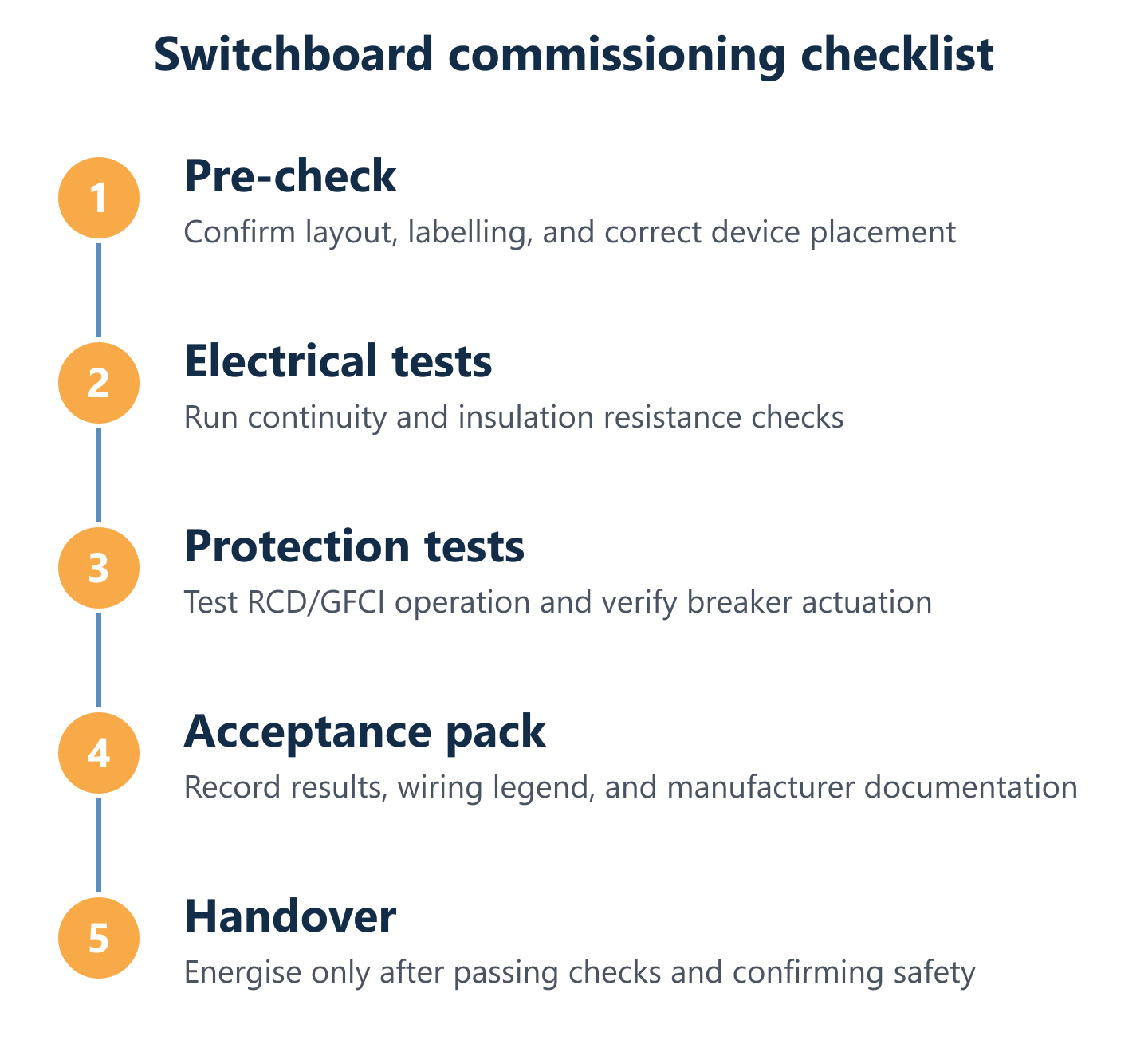
Commissioning is not a formality — it is the stage at which the installation is verified to be safe and correct before it is handed over for use. A board that has been carefully planned and assembled can still contain wiring errors, insulation faults, or incorrectly rated protective devices that are only revealed through systematic testing. Skipping or abbreviating commissioning checks transfers that risk to the end user and to anyone who services the board later.
The commissioning sequence for a typical switchboard installation covers the following areas:
- Visual inspection: verify all components are correctly seated, all conductors are terminated and labelled, no exposed live parts are accessible, and the wiring legend matches the physical installation.
- Continuity checks: confirm protective earth continuity from each circuit's earth terminal back to the PE bus bar before energising.
- Insulation resistance test: with all breakers open and the supply disconnected, measure insulation resistance between live conductors and earth; values below 1 MΩ indicate a fault requiring investigation before energising.
- Polarity verification: confirm that phase and neutral conductors are correctly identified and terminated at every circuit outlet.
- RCD/GFCI trip-time testing: test each residual current device at rated trip current; devices that do not trip within the manufacturer's specified time must be replaced before commissioning is complete.
- Circuit protection coordination check: verify that each MCB rating is appropriate for the cable cross-section it protects and the load it serves.
- Functional test: energise each circuit in sequence, confirming correct operation and that no unintended tripping occurs under normal load.
At Impulso Tecnológico, we support the operational side of commissioning — configuration, reprogramming, and technical service alignment — particularly where the switchboard installation is part of a broader managed environment spanning multiple sites. This coordination reduces downtime risk and ensures that communications infrastructure, including VoIP and hybrid telephony systems, remains stable throughout the commissioning process.
Pre-energisation verification: continuity, insulation, and polarity checks
Pre-energisation verification is the last opportunity to catch wiring errors without consequence. Three tests are non-negotiable. First, continuity: use a low-resistance ohmmeter to verify that the protective earth conductor forms a complete, low-impedance path from each circuit's earth terminal to the main PE bus bar. A reading significantly above zero indicates a broken or incorrectly terminated earth conductor.
Second, insulation resistance: with all circuit breakers open and the incoming supply isolated, apply a test voltage (typically 500 V DC for installations rated up to 500 V AC) between each live conductor and earth. A healthy installation will show values well above 1 MΩ per circuit; anything lower warrants investigation before energising. Third, polarity: confirm that phase and neutral are not transposed at any outlet or terminal. Transposed polarity is invisible to a continuity test but creates a shock risk at switched outlets and can damage equipment with polarised inputs.
RCD/GFCI and circuit protection considerations: selecting and testing protection per circuit
Residual current devices (RCDs) — also referred to as GFCIs in North American terminology — protect against earth leakage currents that circuit breakers alone cannot detect. Selecting the correct RCD type and sensitivity for each circuit is a design decision, not an afterthought. General-purpose socket circuits typically require a 30 mA RCD for personal protection; circuits serving equipment with significant earth leakage (variable-speed drives, IT equipment) may need a 100 mA or 300 mA device to avoid nuisance tripping.
RCD testing must be performed before commissioning is complete. Use a dedicated RCD tester to verify that each device trips within its rated disconnection time at the rated residual current. Also test at 50% of rated current to confirm the device does not trip spuriously. Record all trip times in the commissioning documentation. Where RCDs protect multiple circuits, verify that a fault on one circuit does not cause disproportionate disconnection of unrelated circuits — a sign that the protection coordination between the RCD and downstream MCBs needs review.
Documentation and quality assurance: passports/certificates, labelling, and acceptance criteria
A completed switchboard installation is only as reliable as its documentation. Before handover, the commissioning pack should include: the manufacturer's passport or certificate for each major component (main switch, RCDs, MCBs), confirming rated values, batch or serial number, and compliance markings; the as-built wiring legend and labelling schedule, updated to reflect any changes made during installation; test records for all pre-energisation checks, including insulation resistance values, continuity readings, and RCD trip times; and a circuit schedule posted inside the enclosure door that matches the wiring legend exactly.
Quality assurance at this stage is also a practical safeguard. If a fault develops six months after commissioning, a complete documentation pack allows the fault to be traced against the original design rather than requiring the board to be re-surveyed from scratch. For organisations working with Impulso Tecnológico across managed IT environments, this documentation integrates with broader asset records, making future maintenance — whether for electrical infrastructure or telephone switchboard maintenance — straightforward and auditable.
A switchboards installation that is planned with clear consumer grouping, sized with adequate spare capacity, wired to a documented schematic, and commissioned with systematic verification does not just pass inspection — it remains dependable under real operating conditions for years. Use the structure in this guide as a working checklist: define scope before ordering, follow the mounting sequence, and complete every pre-energisation and RCD test before the board is handed over. For organisations that need installation, configuration, or ongoing managed support — including integration with VoIP or hybrid telephony environments — business phone system installation and business telephone switchboard solutions from Impulso Tecnológico are available with a no-commitment estimate.