
Computer network cabling is the physical layer of wired connectivity that links devices, servers, and communication systems across a building or campus. It encompasses copper and fibre cables, patch panels, racks, and termination points — all working together to carry data, voice, and video reliably between endpoints.
Poor cabling is the most common root cause of intermittent connectivity, unexplained packet loss, and failed Wi-Fi deployments. Yet it is also the easiest layer to get right when the project is planned properly. The challenge for most organisations is that cabling decisions made today — cable category, shielding, routing, and documentation — directly affect how much downtime and rework they face over the next decade.
This guide covers every stage of a professional cabling project: understanding the components, choosing between cable types, following a structured installation workflow, and validating links with proper testing. Whether you are planning a new office fit-out, upgrading an ageing Cat5e infrastructure, or standardising cabling across multiple sites, the sections below give you the technical grounding and decision criteria to move forward with confidence.
What computer network cabling is (and what it connects)
Computer network cabling is the physical medium through which digital signals travel between every device on a network — workstations, IP phones, cameras, servers, switches, and wireless access points. It is not simply wire in a wall; it is a designed system with defined pathways, termination standards, and performance thresholds that determine whether a link meets its rated speed and distance.
At Impulso Tecnológico, cabling is treated as an integral part of the broader IT environment rather than a standalone physical task. That means the design, component selection, workmanship, and structured cabling certification all align with the operational requirements of the office or data environment being served — not just the minimum spec needed to pass a basic continuity test.
The table below maps the main cabling signals to their typical applications and infrastructure requirements:
| Signal type | Typical application | Minimum cable standard | Key infrastructure requirement |
|---|---|---|---|
| Data (Ethernet) | Workstations, servers, switches | Cat5e (1 Gbps), Cat6 (10 Gbps to 55 m) | Patch panels, structured runs ≤90 m |
| Voice (VoIP) | IP desk phones, PBX systems | Cat5e minimum; Cat6 recommended | PoE-capable switch ports, labelled outlets |
| Video (IP cameras, conferencing) | Surveillance, video conferencing endpoints | Cat6 or Cat6a for 4K streams | PoE+ budget planning, dedicated VLAN routing |
| Backbone (inter-floor/inter-building) | Core switch interconnects, data centres | OM3/OM4 multi-mode or OS2 single-mode fibre | Fibre patch panels, splice enclosures |
Core components: endpoints, patch panels, racks, and backbone
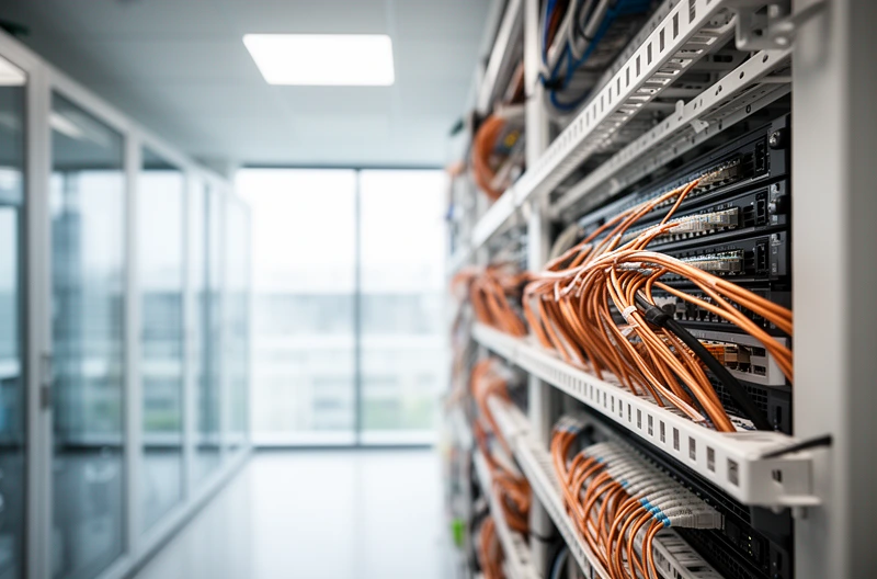
Every structured cabling installation connects the same core components, regardless of scale. Endpoints — wall outlets, floor boxes, or ceiling drops — terminate the horizontal cable run at the device side. Those runs connect back to patch panels housed in communications racks or cabinets, where administrators make and change connections using short patch leads. The rack also houses switches, routers, and power distribution units.
The backbone layer links distribution frames on different floors or buildings, typically using fibre optic cabling for its distance and bandwidth advantages. Properly designed racks with cable management arms and labelled patch panels are what separate a certified installation from a tangled mess that no one can fault-find six months later. Impulso Tecnológico's server room and communications rack installations follow this structured approach as standard, ensuring every component is documented and accessible.
Signals and use-cases: data, VoIP, and video conferencing
A single Cat6 cable can carry data, VoIP, and video conferencing traffic simultaneously when the network is correctly segmented with VLANs — but the physical cabling must be installed to the right standard first. VoIP phones typically draw power over the cable via Power over Ethernet (PoE), which means the cable must meet both electrical and data performance requirements. Video conferencing endpoints, particularly those streaming 4K content, generate sustained high-bandwidth traffic that exposes any marginal cable run.
Data and voice cabling that was installed to Cat5e in the early 2000s is increasingly a bottleneck for modern unified communications platforms. Organisations running Microsoft Teams Rooms or Cisco video conferencing on legacy infrastructure often find that intermittent call drops trace back to near-end crosstalk (NEXT) failures in ageing copper runs — a problem that proper Cat6 or Cat6a installation eliminates at source.
Structured cabling basics: pathways, administration, and labelling
Structured cabling is a standardised approach to network infrastructure design that organises all cabling into defined subsystems: entrance facilities, equipment rooms, backbone cabling, telecommunications rooms, horizontal cabling, and work-area components. The TIA-568 and ISO/IEC 11801 standards define how each subsystem should be installed and documented.
The practical benefit of structured cabling over ad-hoc point-to-point wiring is administrative clarity. When every outlet carries a unique label that maps to a patch panel port and a floor plan record, a technician can isolate a fault or move a workstation in minutes rather than hours. Cable management and labelling also reduce the risk of accidental disconnection during maintenance and make it straightforward to add capacity as headcount grows. Impulso Tecnológico delivers structured cabling certification as part of every installation, providing clients with documented evidence that links meet the rated performance standard.
Main types of network cabling and when to use each
Choosing the wrong cable type is an expensive mistake — not because the material cost is high, but because rework means pulling cables through conduit, re-terminating, and re-testing after the ceiling tiles are back in place. The four main cable families each have a defined role in a modern network, and the choice between them depends on distance, bandwidth target, electromagnetic environment, and budget.
Impulso Tecnológico supports structured cabling categories 5e, 6, and 7 as well as fibre optic cabling across Spain, selecting manufacturer-approved components — including AMP NETCONNECT professional components — to match the specific requirements and certification targets of each project. The overview below maps each cable family to its primary use-case:
- Unshielded twisted pair (UTP) copper — the default choice for horizontal office runs up to 90 metres; available in Cat5e, Cat6, and Cat6a grades with increasing bandwidth and noise rejection.
- Shielded twisted pair (STP/FTP/SFTP) — required in electrically noisy environments such as factory floors, plant rooms, or buildings with dense fluorescent lighting; adds cost and grounding complexity.
- Fibre optic — the correct solution for backbone runs between floors or buildings, data centre interconnects, and any link exceeding 100 metres; immune to electromagnetic interference and supports multi-gigabit speeds over long distances.
- Coaxial cable — largely superseded in data networks but still found in legacy CCTV systems, cable TV distribution, and some industrial serial applications; not recommended for new structured cabling projects.
Ethernet twisted pair: Cat5e, Cat6, and Cat6a selection logic
Cat5e supports 1 Gbps at up to 100 metres and remains adequate for basic office workstations, but it offers no headroom for 10 Gbps switching — a standard that is now common in mid-range office switches. Cat6 supports 10 Gbps up to 55 metres and 1 Gbps to 100 metres, making it the practical minimum for any new installation where the network will be refreshed within the next five to seven years.
Cat6a extends 10 Gbps to the full 100-metre channel length and is the correct choice for access points running Wi-Fi 6 or Wi-Fi 6E (which can exceed 1 Gbps aggregate), IP cameras requiring sustained high-bandwidth streams, and any run where future-proofing justifies the modest additional cable cost. Cat7 uses a fully shielded construction and GG45 or TERA connectors, which can complicate termination and interoperability; most projects are better served by Cat6a UTP or Cat6a STP depending on the electromagnetic environment.
Fibre optic cabling: single-mode vs multi-mode and backbone planning
Fibre optic backbone design starts with a distance and bandwidth calculation. Multi-mode fibre (OM3 or OM4) supports 10 Gbps to 300 metres (OM3) or 400 metres (OM4) and is cost-effective for intra-building backbones because the transceivers are cheaper than single-mode equivalents. OM4 is the current standard for new multi-mode installations; OM5 adds wideband support for emerging 40/100 Gbps applications.
Single-mode fibre (OS2) uses a narrower 9-micron core and laser light sources to achieve distances of 10 km or more at 10 Gbps and beyond — the correct choice for campus backbones, inter-building links, or any future dark-fibre lease scenario. When planning a fibre optic backbone, the key decisions are: connector type (LC is now standard for most enterprise applications), splice method (fusion splicing for permanent joints, mechanical for temporary or emergency repairs), and slack management at each end for future re-termination.
UTP vs STP: shielding trade-offs for noisy environments
Unshielded twisted pair is the right choice for the vast majority of office environments. Its lower cost, simpler termination, and tolerance of imperfect grounding make it practical to install at scale. The twist rate in each pair provides sufficient noise rejection for standard office electromagnetic conditions.
Shielded cable — whether foil-shielded (FTP/ScTP), individually shielded pairs (STP), or both (SFTP/S/FTP) — becomes necessary when cables run near high-voltage power cables, variable-frequency drives, industrial machinery, or dense lighting rigs. The critical requirement with any shielded installation is a continuous, low-impedance ground path from the shield at each end back to the rack earth. A shielded cable with a broken or floating ground performs worse than a well-installed UTP run because the shield itself becomes an antenna. Impulso Tecnológico's engineers assess the electromagnetic environment during the initial site survey to determine whether shielding is genuinely required or whether careful cable routing achieves the same result at lower cost.

Choosing and validating cabling: from design to testing
Selecting the right cable type is only the first decision. The quality of the outcome depends equally on how the installation is planned, executed, and verified. A Cat6a cable installed with excessive bend radius, poor RJ45 termination and testing practice, or missing documentation provides none of the performance guarantees its specification promises.
Impulso Tecnológico's methodology starts with a free on-site consultation to understand current and future requirements, followed by a fixed-price quote that removes budget uncertainty. Installation is carried out using manufacturer-approved components, and every project concludes with structured cabling certification — documented test results that confirm each link meets its rated standard. The criteria that drive the design and validation process are:
- Required bandwidth and speed: current switching standard plus at least one technology generation of headroom (e.g., Cat6a for 10 Gbps if the switch estate will be refreshed within five years).
- Channel length: measure actual cable routes, not floor plan distances — routes through conduit, above suspended ceilings, and around structural elements add 20–40% to straight-line measurements.
- Electromagnetic environment: identify proximity to power distribution boards, motors, and lighting circuits before specifying UTP or STP.
- PoE budget: calculate the total PoE load on each switch port and cable run to confirm the conductor gauge and cable category can handle the current without excessive heat rise.
- Growth and scalability: plan spare outlets (typically 20–25% above current headcount) and reserve conduit capacity for future cable pulls.
- Documentation standard: agree on labelling convention, floor plan records, and test report format before installation begins — retrofitting documentation is disproportionately expensive.
Decision checklist: requirements, cable type, network design, and growth
Before specifying a single metre of cable, answer these questions in writing: What is the maximum link speed required today, and what will it be in five years? What is the longest horizontal run from the telecommunications room to the furthest outlet? Are there any sections of route that pass through electromagnetically hostile areas? What PoE devices will be connected, and what is the aggregate power draw per switch? How many additional workpoints are likely to be added in the next three years?
The answers determine category (Cat6 vs Cat6a vs fibre), shielding requirement (UTP vs STP), conduit sizing, patch panel port count, and switch PoE budget. Network infrastructure design that accounts for growth avoids the costly scenario of pulling new cables through already-occupied conduit two years after installation.
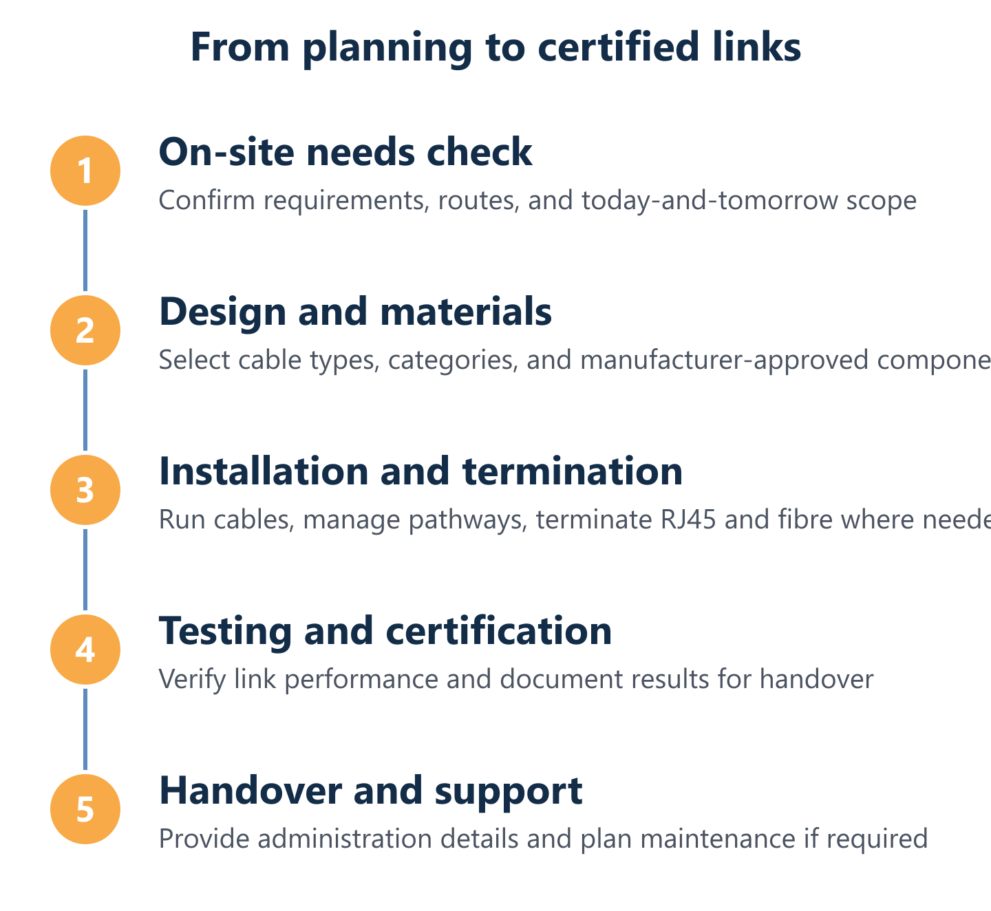
Installation workflow: planning, termination, cable management, and documentation
A professional installation follows a defined sequence. First, the site survey confirms cable routes, conduit availability, rack locations, and any existing cabling to be retained or removed — including abandoned cables, which add fire load and obstruct future pulls. Second, materials are specified and ordered to the agreed standard, using manufacturer-approved components to support the certification target.
During installation, horizontal runs are pulled without exceeding the cable's minimum bend radius (typically four times the cable diameter for UTP) and are secured at regular intervals. RJ45 termination uses the T568B wiring standard unless the client specifies otherwise, with the untwisted length at the connector kept to the minimum the connector design allows — typically under 13 mm for Cat6. Cable management and labelling are applied at every patch panel port and wall outlet before testing begins. Documentation — as-built drawings, outlet schedules, and test reports — is delivered at project handover.
Testing and diagnosis: what to measure and how to handle common faults
Certification testing with a calibrated cable analyser (such as a Fluke DSX or equivalent Level IV tester) measures the parameters that determine real-world performance: wiremap (correct pin-to-pin continuity), length, insertion loss, near-end crosstalk (NEXT), power sum NEXT (PSNEXT), return loss, and propagation delay skew. Every parameter must pass the limits defined by the relevant standard (TIA-568-C.2 for Cat6, ISO/IEC 11801 for international projects) before a link is considered certified.
The most common faults found during testing are: split pairs (incorrect termination causing catastrophic NEXT failure), excessive untwist at the connector (NEXT failure at high frequencies), damaged cable from staple or cable tie overtightening (return loss failure), and runs that exceed the 90-metre permanent link limit. Each fault has a clear remediation: re-terminate, re-route, or replace the affected section. Impulso Tecnológico also provides network maintenance and ongoing support for certified cabling, ensuring that the infrastructure continues to perform as the environment changes.
Get the cabling right at installation — with the correct category, proper RJ45 termination, certified test results, and complete documentation — and every subsequent network upgrade becomes a switch or software change rather than a construction project. Impulso Tecnológico has been delivering certified structured cabling installations across Spain for more than fifteen years, combining manufacturer-approved components with a client-led methodology that covers everything from the initial site survey to post-installation maintenance. If your organisation is planning a new office fit-out, a cabling upgrade, or needs to standardise infrastructure across multiple sites, our team is ready to advise. Explore our structured cabling services or learn how we approach network infrastructure maintenance to keep certified installations performing over the long term.