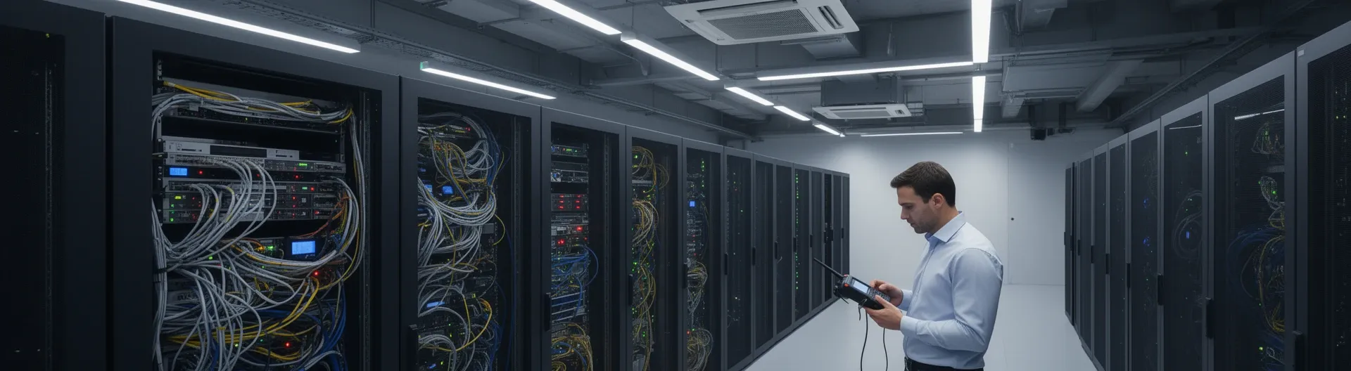

Assembling server rooms and communication racks means integrating room-level infrastructure—power distribution, airflow containment, grounding, and cable pathways—with the mechanical build and structured cabling of individual racks and communication frames. Done correctly, the result is a certified, maintainable environment that supports current operations and future growth.
Many organisations treat rack assembly as a standalone task, disconnected from room readiness. That disconnect is where problems begin: overheating from poor airflow planning, power failures traced to absent UPS integration, or cabling nightmares caused by skipping labelling discipline during installation. The physical assembly of racks and communication frames is only half the work; the other half is ensuring the room itself—its power routes, ventilation paths, floor loading, and safety compliance—supports everything mounted inside those racks.
This guide covers the full scope, from site preparation and room build-out through rack selection, step-by-step assembly, structured cabling management, and post-build verification. Whether you are commissioning a new server room or reorganising an existing one, following a structured approach from the outset prevents costly rework and ensures the environment is ready for certification and long-term operation.
Scope and prerequisites for assembly of server rooms and communication racks
Before a single rack bolt is tightened, the scope of the project must be defined in writing. "Assembly of server rooms and communication racks" spans two distinct but interdependent domains: the physical room infrastructure and the individual rack or communication frame. Conflating or ignoring either domain leads to rework, failed certifications, or operational instability from day one.
At Impulso Tecnológico, our pre-project process starts with a free on-site consultation to map business requirements and network installation needs—both current and projected. From that baseline, we produce a tailored infrastructure plan rather than a generic rack-and-cable solution. With more than fifteen years of structured cabling and data centre installation experience across Spain, our certified engineers translate those requirements into a clean, documented, and certification-aligned environment.
The table below compares the key scope dimensions across the two assembly domains to clarify inputs, constraints, and deliverables before any physical work begins:
| Scope dimension | Room-level assembly | Rack / communication frame assembly |
|---|---|---|
| Primary inputs | Floor plans, power drawings, HVAC specs, access routes | Equipment list, rack data sheets, cabling schedule |
| Key constraints | Floor load rating, ceiling height, fire suppression zones | Rack depth/height (U count), weight per shelf, cable bend radius |
| Critical deliverables | Containment layout, grounding schematic, power distribution map | Populated rack diagram, labelled patch schedule, test certificates |
| Compliance reference | EN 50173, local building regulations, GDPR (data zone segregation) | TIA-942, ISO/IEC 11801, manufacturer installation guides |
| Typical rework risk if skipped | Cooling failures, anchoring failures, emergency cabling changes | Cable congestion, equipment incompatibility, failed link tests |
What "assembly" means at room level vs rack level
Room-level assembly covers containment, airflow, power distribution, segregation, and grounding—not only rack placement. At this scale, decisions about hot-aisle and cold-aisle separation, raised-floor or overhead cable routing, and the location of UPS units and power distribution units (PDUs) determine whether the environment will remain stable under load. Room-level work also includes fire suppression integration, access control placement, and environmental monitoring for temperature and humidity. These are structural decisions: changing them after racks are populated is expensive and disruptive. Getting them right before installation begins is the single most effective way to protect the investment in equipment and cabling that follows.
Key prerequisites: drawings, load plan, and access constraints
Rack and communication frame assembly focuses on mechanical build, equipment fit, and cable pathways for structured cabling. Before assembly starts, three documents must be in place: an accurate floor plan with rack positions and clearances marked, a load plan confirming the floor can support the combined weight of populated racks (a fully loaded 42U rack can exceed 900 kg), and an access constraint map identifying door widths, lift capacities, and corridor clearances that affect how racks are moved into position. Communication frames—typically open-frame or shallow-depth enclosures used for patch panels, switches, and fibre distribution—have their own depth and airflow requirements that differ from server racks and must be specified separately in the drawings.
Deliverables: organised pathways, labelling, and certification-ready documentation
Starting with clear requirements and documentation targets avoids rework during mounting and cabling. The expected deliverables for a well-assembled server room and communication rack environment include: an as-built rack elevation diagram showing every device and its U position; a structured cabling schedule with port-to-port labelling; cable tray routing drawings; grounding continuity test records; and link performance test certificates for every installed run. At Impulso Tecnológico, structured cabling certification is included as standard in our delivery, which is particularly relevant when racks and server rooms must meet operational and audit requirements. Agreeing on these deliverables before work starts means every installation decision—cable route, label format, patch panel position—is made with the final documentation in mind, not retrofitted afterwards.

Site preparation and room build-out for reliable operation
Room readiness is the foundation on which every rack assembly decision rests. A rack installed in a room with inadequate power routing, poor ventilation, or an unverified floor load rating will underperform regardless of how precisely the rack itself is assembled. Site preparation is not a preliminary formality—it is a technical phase with its own sequence, checks, and sign-off criteria.
Impulso Tecnológico supports end-to-end cabling execution around server rooms and communication rack spaces across Spain, with nationwide coverage from our Madrid base. Our teams have handled installations ranging from single-rack comms rooms in SME offices to multi-rack deployments in industrial and logistics environments, and the preparation phase follows the same disciplined sequence regardless of scale.
The room build-out should proceed in this order:
- Survey and document the existing space: Record floor dimensions, ceiling height, existing power circuits, HVAC positions, and structural load data before any design decision is made.
- Define rack positions and aisle layout: Mark hot-aisle and cold-aisle zones, confirm minimum 1,000 mm front clearance and 600 mm rear clearance per rack row for maintenance access.
- Plan power distribution: Identify UPS placement, PDU type (horizontal vs vertical), circuit capacity per rack, and cable entry routes from the electrical panel.
- Design the ventilation and containment strategy: Specify airflow direction per rack, containment curtains or doors if needed, and supplementary cooling units if the room HVAC is insufficient.
- Prepare cable entry points and tray routes: Install cable trays, conduits, and floor cut-throughs before racks arrive so cabling can be routed cleanly from day one.
- Verify floor anchoring points: Confirm that anchor bolts or anti-tip brackets can be fixed to the floor structure at each rack position.
- Install environmental monitoring: Place temperature and humidity sensors at intake and exhaust points before equipment is powered on.
Power, UPS/PDUs, and cable entry planning for the room
Power planning must be completed before racks are positioned, not after. Each rack's power draw should be calculated from the equipment list—including worst-case load figures—and the UPS capacity sized to cover that load plus a minimum 20% headroom for future expansion. UPS units should be positioned to minimise cable run length to PDUs, reducing voltage drop and simplifying maintenance. PDUs should be specified as rack-mounted vertical units where possible, freeing U space for active equipment. Cable entry points into the room—whether through raised-floor tiles, wall conduits, or overhead trays—must be sealed after installation to maintain fire compartmentalisation. Labelling power circuits at the panel and at each PDU inlet is not optional; it is a safety and maintenance requirement that pays dividends during any future fault-finding exercise.
Ventilation and airflow strategy: containment, hot/cold separation, and clearances
Server room airflow design is one of the most consequential decisions in the build-out, yet it is frequently underspecified. The standard approach—alternating cold-aisle and hot-aisle rack rows—works only when containment is enforced. Without blanking panels in unused rack Us, cold air bypasses equipment and mixes with hot exhaust air, raising inlet temperatures across the room. Each unused U in a populated rack should be fitted with a blanking panel before equipment is powered on. For higher-density deployments, containment curtains or enclosed aisle systems significantly improve cooling efficiency. Clearances matter too: a minimum of 1,200 mm in front of racks allows for equipment extraction and trolley access; rear clearance of at least 600 mm is required for hot-air exhaust to escape freely to return air paths or supplementary cooling units.
Floor readiness, anchoring, and safety compliance at room scale
Floor strength is a non-negotiable prerequisite. Standard office floors are typically rated at 250–500 kg/m², while a row of fully loaded server racks can concentrate loads well above 1,000 kg/m² in a narrow footprint. If the structural survey identifies a shortfall, options include distributing rack weight across spreader plates or relocating the server room entirely—neither is cheap to discover after installation. Anchoring racks to the floor using manufacturer-specified brackets prevents tip hazards and is required under most workplace safety regulations in Spain and the EU. Anti-seismic bracing should be considered in geologically active regions. Grounding at room scale means connecting the rack bonding conductors to a dedicated earth bar, which in turn connects to the building's main earthing system—not to a convenient nearby socket earth.
Step-by-step assembly and structured cabling workflow
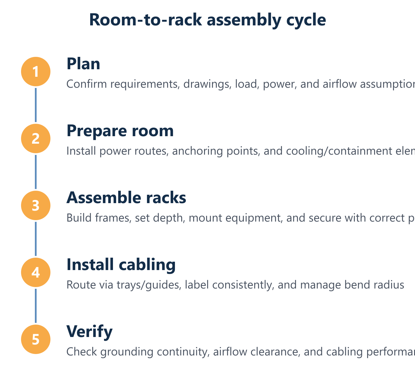
With the room prepared and documented, rack and communication frame assembly follows a repeatable workflow. The discipline here is sequential: assemble the mechanical structure completely before mounting equipment, mount equipment before running cables, and run cables before labelling and testing. Skipping steps or running tasks in parallel introduces errors that are expensive to correct once the rack is populated.
Impulso Tecnológico delivers organised rack cabling paths and structured cabling certification as part of every installation. Our scope includes cabling tray installation for racks, the links between cabling and communication frames, and support for cleaning and organising existing cabling where a room is being upgraded rather than built from scratch. Our structured cabling installations cover categories 5e, 6, 7, and fibre, with certification included as standard.
The following signals indicate a well-executed assembly process—use them as quality checkpoints throughout the build:
- All rack components are assembled in the manufacturer's specified order, with adjustable beams set to the correct depth index before any equipment is mounted.
- Screws are finger-tightened first across all joints, then torqued in the correct fastening pattern (typically corner-to-corner, not sequential) to prevent frame distortion.
- Equipment is mounted from the bottom of the rack upwards, with heavier items (UPS, PDUs, patch panels) positioned low to keep the centre of gravity stable.
- Blanking panels fill every unused U before the rack is considered complete.
- Cable management arms and horizontal cable guides are installed at the correct intervals before cables are routed—not retrofitted afterwards.
- Every cable run is labelled at both ends before it is dressed and secured, using a consistent labelling scheme agreed in the pre-build documentation.
- Grounding continuity is verified with a multimeter at each rack before power is applied.
Rack and communication frame assembly: tools, order, and fastening discipline
Assemble racks and communication frames with correct orientation, depth settings, and stable fastening patterns. The required tools are straightforward—pozidriv and hex screwdrivers, a torque screwdriver set to the manufacturer's specification, a spirit level, and a tape measure—but their disciplined use separates a stable rack from one that develops looseness under vibration. Begin by identifying all components against the packing list; missing a side panel or a cage nut strip at this stage is far easier to resolve before assembly than after. Set adjustable vertical rails to the correct depth using the index numbers marked on the beams: this determines equipment fit for the entire rack's life. Assemble side panels and top/bottom frames before inserting vertical rails. Once all joints are finger-tight and the frame is confirmed square with a spirit level, apply the fastening pattern—typically diagonally opposite corners first—to distribute stress evenly across the frame. For our structured cabling and data centre rack installation projects, Impulso Tecnológico's engineers follow manufacturer-specific assembly guides as a baseline, supplemented by our own installation standards developed over fifteen years of deployments across Spain.
Mounting and internal layout: cooling, spacing, shelves, and expansion planning
Manage cables as an installation workflow: routing space, guide direction, and consistent labelling must be planned before the first cable is pulled. Internal rack layout directly affects airflow, maintenance access, and the ability to add equipment later. Patch panels and switches belong at the top of the communication frame (or at a dedicated patching zone), with active equipment below and power distribution at the base. Leave at least 1U of space between high-heat devices to allow exhaust air to escape before it reaches the next device's intake. Shelves for non-rack-mountable equipment should be positioned so they do not obstruct airflow paths—perforated shelves are preferable to solid ones. Reserve a minimum of 20% of total U space for future expansion; a rack that is 100% populated on day one has no room to grow and forces disruptive reorganisation within months. Horizontal cable management panels (1U) should be installed between every two patch panel rows to keep structured cabling routes clean and accessible without disturbing active connections.
Cable management and labelling for structured network cabling, plus verification
Verify ventilation, grounding continuity, and cabling performance before handover. Structured cabling management is not a cosmetic exercise—it directly affects signal integrity, fault resolution time, and the ability to make changes without service disruption. Route power cables and data cables on opposite sides of the rack wherever possible, using dedicated vertical cable management channels. Secure cables with hook-and-loop fasteners (not cable ties that cannot be released without cutting) at regular intervals, maintaining the manufacturer's minimum bend radius for the cable category in use. Every run must be labelled at both ends with a unique identifier that matches the as-built documentation. Once cabling is complete, verify grounding continuity at each rack earth point, check that all blanking panels are in place, confirm airflow is unobstructed by cables, and run link performance tests on every structured cabling run. For fibre, OTDR traces should be included. Impulso Tecnológico provides structured cabling certification as part of our delivery, producing the test records that support both operational sign-off and future audit requirements. Our computer network cabling and structured cabling services are designed to deliver exactly this level of documented, certified completion.
A server room and its communication racks perform as a single system—not as a collection of independently assembled components. When the room build-out, rack assembly, structured cabling installation, and post-build verification are treated as one integrated workflow, the result is an environment that is safe, certified, and ready to support the business without surprises. Impulso Tecnológico's approach to server installation and network infrastructure maintenance follows this same principle: plan thoroughly, execute precisely, and hand over with complete documentation. If your organisation is planning a new server room, expanding an existing one, or reorganising a communication rack environment, contact Impulso Tecnológico for a free on-site consultation and a fixed-price quote.