

Computer network installation is the process of designing, physically cabling, configuring, testing, and documenting a business network — covering everything from structured cabling and hardware setup to security controls and handover certification. A professional installation delivers a reliable, scalable, and secure foundation for all business operations that depend on connectivity.
Most network problems that surface six or twelve months after go-live — dropped connections, bandwidth bottlenecks, security gaps, or unmanageable cable runs — trace back to decisions made (or skipped) during the original installation. Choosing the wrong cable category for the distances involved, skipping VLAN segmentation, or failing to document the final layout all create compounding costs later. The difference between a network that simply works on day one and one that remains workable as the business grows lies in the rigour applied at every stage: site assessment, design, physical build, configuration, testing, and structured handover. This guide covers each stage in sequence, with the criteria and practical detail needed to plan, commission, or evaluate a professional computer network installation.
What "computer network installation" includes (from site to security)
A professional computer network installation is not simply pulling cable and plugging in a switch. It spans three distinct but interdependent layers: the physical infrastructure (cabling, racks, patch panels, access points), the logical network configuration (IP addressing, VLANs, firewall rules, wireless security), and the operational layer (documentation, labelling, test results, and the maintenance framework that follows). Skipping or compressing any of these layers creates risk — either immediately, in the form of connectivity failures, or over time, as undocumented changes accumulate and troubleshooting becomes guesswork.
At Impulso Tecnológico, our structured cabling and certified network infrastructure service across Spain covers all three layers. After a free on-site consultation and fixed-price quotation, our engineers design, install, assemble, certify, and maintain the network — from single-workstation wiring to large-scale environments including data centres and server racks. The scope is defined before work begins, so clients understand exactly what will be delivered and tested.
| Installation component | Minimum scope | Professional scope |
|---|---|---|
| Physical cabling | Cable runs installed | Certified Cat6/Cat6a/fibre, labelled, tested, documented |
| Network hardware | Switch and router connected | Managed switches, configured VLANs, redundant uplinks where required |
| Wireless | Access point installed | Wi-Fi access point installation with coverage survey, WPA3, SSID segmentation |
| Security | Default firewall enabled | Firewall rules, access controls, guest isolation, endpoint policy |
| Testing and validation | Ping test | Cable testing and certification, performance under load, security validation |
| Documentation | None or informal | Network documentation: as-built drawings, port schedules, test reports |
Scope map: physical layer, network layer, and operations layer
Think of a computer network installation in three stacked layers, each dependent on the one below it. The physical layer covers structured cabling (Cat5e through Cat7, fibre optic cabling), patch panels, cabling trays, rack assembly, and the physical placement of switches and access points. The network layer covers logical configuration: IP addressing and subnets, VLAN segmentation, routing, firewall policy, and wireless security settings. The operations layer covers what happens after handover — network documentation, labelling conventions, monitoring baselines, and the maintenance procedures that keep the network stable. A gap at the physical layer (poorly terminated cables, incorrect category for the run length) cascades upward into unreliable logical connectivity and unpredictable performance. Professional installation addresses all three layers before the network is accepted.
Deliverables you should expect: certification, labelling, and test results
A completed network installation should produce a defined set of deliverables, not just a working connection. Cable testing and certification reports confirm that each run meets the performance specification for its category — attenuation, return loss, and propagation delay are measured, not assumed. Every cable, patch panel port, wall plate, and switch port should carry a consistent label that matches the as-built network documentation. That documentation should include a floor plan or rack diagram showing cable routes, port assignments, IP address allocations, VLAN definitions, and wireless SSID configurations. Without these deliverables, the first engineer to troubleshoot a fault after handover is working blind. At Impulso Tecnológico, structured cabling certification is included as part of the installation service, so clients receive test evidence alongside the completed infrastructure.
Where security controls fit during installation (not after)
Security configuration is most effective — and least disruptive — when it is built into the installation from the start rather than retrofitted. During network switch configuration, managed switches should be set up with VLAN segmentation that separates traffic by function: corporate devices, guest users, IoT or building systems, and servers should not share the same broadcast domain. Wireless access points should be configured with WPA3 where supported, with separate SSIDs for staff and visitors, and with client isolation enabled on guest networks. Firewall rules should be defined and applied before any device connects to the production network. Access control policies — including which VLANs can reach which resources — are far easier to implement correctly on a clean network than to enforce on one that has already been in use. Treating security as an installation deliverable, not an afterthought, is the standard Impulso Tecnológico applies across every network project.

Planning and design that prevents rework
The most expensive network installation mistakes happen before a single cable is pulled — they happen in the planning phase, or rather in the absence of one. A network designed around today's headcount without accounting for growth, or one where cable routes were chosen without checking for interference from electrical conduit, will require disruptive rework within a few years. At Impulso Tecnológico, our methodology begins by understanding the client's business context: how the organisation operates, what applications and systems depend on the network, and what the environment will look like in three to five years. From that understanding, we design an infrastructure tailored to effective operation and certified cabling practices — not a generic template.
A structured planning process moves through these phases:
- Site survey: measure distances, identify cable pathways, locate rack positions, and flag environmental constraints (existing electrical routes, ceiling heights, fire barriers).
- Requirements assessment: count users and devices, identify bandwidth-intensive applications (video, VoIP, cloud services), define coverage targets for wireless zones, and confirm budget parameters.
- Topology design: select wired, Wi-Fi, or hybrid architecture; define LAN/WAN boundaries; plan VLAN segmentation; specify QoS requirements for latency-sensitive traffic.
- Hardware and cable specification: choose cable categories (Cat6, Cat6a, fibre optic cabling) based on run lengths and bandwidth targets; specify managed switches, access points, and firewall hardware.
- Capacity and growth planning: add spare data points (typically 20–30% above current count), specify patch panel capacity, and document assumptions for future expansion.
- Risk review: identify route conflicts, power separation requirements, and single points of failure before installation begins.
Requirements checklist: users, applications, bandwidth, and coverage targets
Before any design work begins, a site survey translates the physical environment into installation constraints. Measure every cable run from the patch panel to the intended data point location — not as a straight line, but following the actual pathway through ceiling voids, conduit, and trunking. TIA-568 sets a 90-metre limit for permanent horizontal cabling (with a further 10 metres allowable for patch leads and equipment cables), so any run approaching that limit needs to be identified and either rerouted or served via a fibre link to an intermediate distribution point. Note the location of electrical conduit and maintain at least 150mm separation for unshielded cable runs, increasing to 300mm near high-voltage equipment. Identify rack locations and confirm that the room or cabinet has adequate power, ventilation, and physical security. These constraints directly shape the topology and cable category decisions that follow.
Topology and segmentation decisions: LAN/WAN, VLAN strategy, and guest separation
The choice between a fully wired network, a wireless-first deployment, or a hybrid architecture is not primarily a cost question — it is a performance and security question. Wired connections via structured cabling deliver deterministic throughput and lower latency, making them the right choice for workstations, servers, VoIP handsets, and fixed equipment. Wi-Fi access point installation extends connectivity to mobile devices, meeting rooms, and areas where cabling is impractical, but wireless capacity is shared and subject to interference. A hybrid architecture — wired backbone with managed wireless overlaid — is the standard for most business environments today. Within that architecture, VLAN segmentation is the primary tool for controlling traffic flows: corporate devices, guest users, IP cameras, and building management systems each belong in separate VLANs with firewall rules governing inter-VLAN routing. QoS policies should be applied at the switch level to prioritise latency-sensitive traffic such as VoIP and video conferencing. These decisions, made at the design stage, determine whether the network remains manageable as the organisation grows.
Risk controls: avoiding cable route mistakes, power separation issues, and bottlenecks
Three categories of planning error account for the majority of post-installation problems. First, cable route conflicts: running data cabling parallel to high-voltage electrical conduit induces interference that degrades signal quality — a problem that is invisible until performance testing reveals it, and expensive to fix once cabling trays are installed. Second, insufficient data point density: planning exactly the number of points currently needed leaves no room for additional workstations, IP phones, or access points without disruptive re-cabling. A minimum 20% spare capacity at the patch panel and additional wall plate positions in flexible areas is a practical baseline. Third, uplink bottlenecks: if access-layer switches connect to the distribution layer via a single 1GbE uplink but the connected devices collectively demand more bandwidth, the uplink becomes the constraint. Specifying 10GbE uplinks or link aggregation at the design stage costs far less than replacing switches after installation. Reviewing these risks explicitly before cabling begins — as part of a structured pre-installation checklist — is standard practice in professional network installations. For organisations planning a server room or communications rack as part of the project, our guide to assembly of server rooms and communication racks covers the physical infrastructure decisions in detail.
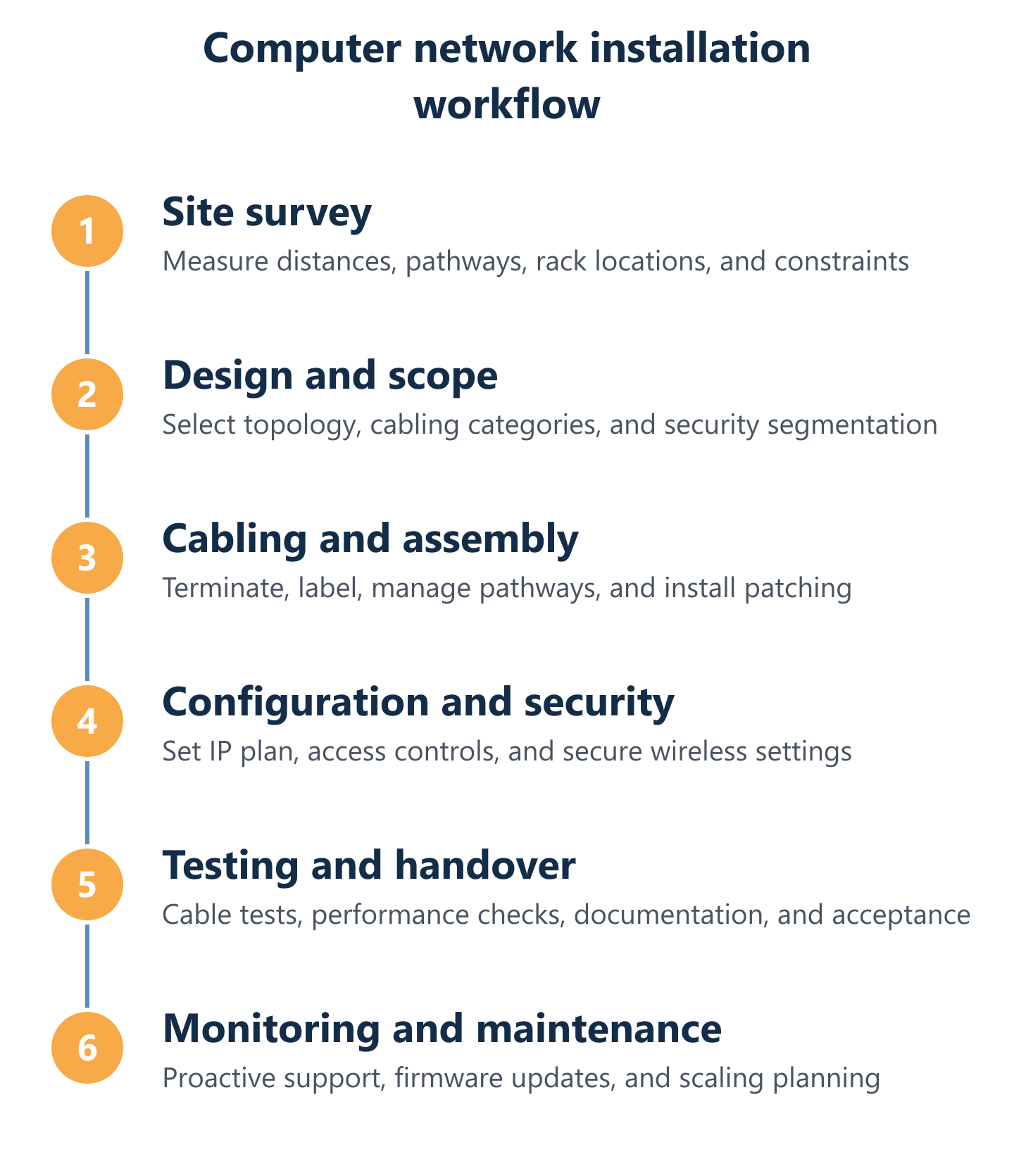
Cabling, configuration, testing, and ongoing monitoring
With a validated design in place, the installation moves through three execution phases — physical build, logical configuration, and testing — before the network is handed over. Each phase has defined outputs that feed into the next, and skipping ahead (configuring switches before cabling is tested, or accepting a network before security validation is complete) introduces risk that is difficult to unwind in a live environment.
At Impulso Tecnológico, our installation capability covers the full execution sequence:
- Structured cabling: Cat5e, Cat6, and Cat7 data cabling; fibre optic cabling for backbone and long-distance runs; voice system cabling for telephony infrastructure.
- Physical infrastructure: cabling tray installation and supply for racks, cabling management systems, rack assembly, and removal of abandoned cables where required.
- Wireless: Wi-Fi access point installation with coverage planning and post-installation validation.
- Certification: structured cabling certification for each completed run, with test results provided as part of the handover documentation.
- Maintenance and emergency support: network maintenance services and emergency cabling issue resolution after the installation is live.
- Consultancy and project management: available for complex or multi-site projects requiring coordination across teams or locations.
For organisations in the capital region, our structured cabling service in Madrid provides the same certified installation standard with local engineer availability.
Structured cabling execution: data points, patching, slack, and pathway management
Structured cabling execution quality is determined by decisions made during the physical build, not correctable after the fact. Each cable run should be measured and cut with adequate slack — typically 300–500mm at each termination point — to allow for clean termination and future re-termination without pulling the cable tight. Cables should be routed through dedicated cabling trays or conduit, separated from power wiring, and secured at regular intervals to prevent sag or strain. At the patch panel, cables should be dressed consistently, with bend radius maintained above the minimum for the cable category (Cat6a is less forgiving than Cat6 due to its larger diameter). Every run is labelled at both ends before termination, using a consistent scheme that matches the network documentation. Fibre optic cabling requires additional care: bend radius limits are stricter, connectors must be clean before mating, and end-face inspection with a fibre microscope is standard practice before testing. These details collectively determine whether the cabling infrastructure passes certification — and whether it performs reliably at the rated category speed over its operational life.
Post-install configuration: IP/subnets, access controls, and WPA3-ready wireless
Network switch configuration begins with a clean, documented IP addressing plan. Assign subnets to each VLAN before connecting any devices: corporate LAN, server VLAN, wireless staff SSID, guest SSID, and any IoT or building systems segment each receive their own subnet and default gateway. DHCP scopes should be sized with headroom — a /24 subnet supports 254 hosts, which is appropriate for most office segments, but server VLANs benefit from static addressing with DHCP reservations. On managed switches, configure port-based VLAN assignments and enable BPDU guard on access ports to prevent spanning tree manipulation. For wireless, deploy WPA3-Personal or WPA3-Enterprise depending on whether a RADIUS authentication server is in scope; disable legacy protocols (WEP, WPA) at the controller level. Guest SSIDs should be isolated from the corporate network at the access point or controller, with client-to-client traffic blocked. Firewall rules should be applied in a deny-by-default posture, with explicit permit rules for required traffic flows only. This configuration baseline, applied consistently across all devices, forms the security foundation that subsequent monitoring and maintenance will build upon.
Validation and handover: cable testing, performance checks, security validation, and documentation
Cable testing and certification is not optional in a professional installation — it is the evidence that the physical layer meets its specification. A cable tester capable of measuring to the relevant TIA or ISO standard (Level III or Level IV accuracy for Cat6 and above) verifies wiremap, length, attenuation, NEXT, and return loss for every run. Fibre runs are tested with an OTDR to identify splice losses, connector quality, and any bends that exceed the minimum radius. Performance testing under realistic load — simultaneous transfers across multiple connections — confirms that the network behaves as designed when actual traffic patterns are applied. Security validation checks that VLAN boundaries are enforced (a device on the guest SSID cannot reach corporate resources), that firewall rules block unauthorised traffic, and that wireless encryption is functioning correctly. All test results, along with as-built network documentation (floor plans, rack diagrams, port schedules, IP address allocations, and VLAN definitions), are compiled into a handover package. This documentation is the starting point for every future maintenance action and the baseline against which changes are tracked. Our broader approach to keeping networks operational after handover is covered in detail in our guide to network infrastructure maintenance.
A computer network installation that is planned carefully, built to certified standards, configured with security from the outset, and handed over with complete documentation does not just work on day one — it remains manageable, auditable, and scalable as the business grows. The investment in rigour at each stage — site survey, design, physical build, configuration, testing, and documentation — pays back through fewer unplanned outages, faster troubleshooting, and a network that can accommodate new requirements without disruptive rework. If you are planning a new installation or assessing an existing network that lacks proper documentation or certification, starting with a structured site assessment is the most effective first step. Impulso Tecnológico offers a free on-site consultation and fixed-price quotation to help you define the scope and budget with clarity before any work begins.